If you've ever wished you could change HF antennas without walking to the feedpoint—or climbing behind the operating desk—this build is for you. With an ESP32 Wi-Fi microcontroller, a 4-channel relay module, and a few SO-239 connectors, you can create a remote antenna switch you control from any phone, tablet, or computer on your network.
Overview
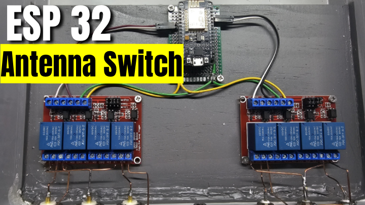
The basic idea is straightforward: each antenna feedline connects to its own relay, and all relays share a common RF output that goes to your transceiver. The ESP32 hosts a small Wi-Fi web server and toggles the relays based on which button you click in the browser. The relays handle the RF path, while the ESP32 handles control logic, Wi-Fi, and the user interface.
Power Rating: In the configuration shown here, this switch is appropriate for transmit power levels up to about 100 watts with typical HF duty cycles. If you routinely run higher power (500W–1500W), treat this project as a control system for external high-power RF relays or commercial coax switches instead of passing RF directly through the PCB relays.
Parts List
- ESP32 Dev Board (ESP-WROOM-32)
- 4-Channel Relay Module (5V, optoisolated version recommended for noise immunity)
- SO-239 female connectors (panel mount) – Four for antennas plus one common output to the radio
- Small 5V power supply (2A minimum) or a quality 5V USB source
- Jumper wires (22–24 AWG) or small hookup wire
- Metal enclosure for RF shielding and mechanical protection
- Optional: Protection diodes, front-panel status LEDs, and screw terminal blocks for cleaner wiring
Choosing the Right Relay Module
Your relay board choice directly affects RF performance and reliability. Look for modules with:
- 10A contact rating (or higher) – Gives comfortable margin for 100W HF service
- Optoisolators – Provide electrical isolation between the ESP32 and relay coils for better stability
- Clearly labeled COM, NO, and NC terminals – Simplifies wiring each RF path correctly
- Active-LOW trigger inputs – The most common style; the relay energizes when the input is pulled LOW
Common options include HiLetgo and Songle SRD-05VDC-based 4-channel boards, which are easy to find from most electronics suppliers and online marketplaces.
Wiring the System
Each relay switches the center conductor of one antenna port onto a shared output that goes back to your transceiver. The relay board inputs (IN1–IN4) connect to ESP32 GPIO pins, and the relay module is powered from 5V with a shared ground between the ESP32 and relay board.
Control Connections:
- Relay IN1 → ESP32 GPIO 23
- Relay IN2 → ESP32 GPIO 22
- Relay IN3 → ESP32 GPIO 21
- Relay IN4 → ESP32 GPIO 19
- Relay VCC → ESP32 5V (or external 5V supply)
- Relay GND → ESP32 GND
RF Connections:
- Antenna 1–4: Connect each coax center conductor to a relay COM terminal
- Common Output: Tie all relay NO (Normally Open) terminals together and connect that junction to the transceiver SO-239 center pin
- Coax shields: Bond all shields securely to the metal enclosure and a common ground point
Important: Only the center conductors should be switched by the relays. Coax shields remain continuously bonded to the enclosure and station ground for proper RF return and noise control.
Power Supply Notes
The ESP32 and relay board can be run from the same 5V source, but relay coils can draw enough current that marginal supplies cause resets or Wi-Fi dropouts. For robust operation:
- Use a 5V / 2A USB supply if powering both ESP32 and relays together, or
- Use a separate 5V / 2A supply for the relay module and share only the ground reference with the ESP32
ESP32 Web Server Code
The sketch below turns the ESP32 into a Wi-Fi access point and simple web server with one button per antenna. Load this into your ESP32 using the Arduino IDE with ESP32 support installed.
// Remote Antenna Switch - ESP32 Web Server
// Author: Danny Davis - BrokenSignal.tv
// Power Rating: Up to 100 watts

#include <WiFi.h>
#include <WebServer.h>

// Wi-Fi credentials for Access Point mode
const char* ssid = "AntennaSwitch";
const char* password = "hamradio";

WebServer server(80);

// Relay control pins (active LOW)
int relays[4] = {23, 22, 21, 19};
String antennaNames[4] = {"Dipole", "Vertical", "Beam", "EFHW"};

// Track currently active relay
int activeRelay = 0;

void handleRoot() {
  String html = "<html><head><title>Antenna Switch</title>";
  html += "<meta name='viewport' content='width=device-width, initial-scale=1'>";
  html += "<style>";
  html += "body { font-family: Arial, sans-serif; text-align: center; background: #1a1a1a; color: #fff; padding: 20px; }";
  html += "h1 { color: #4CAF50; }";
  html += ".button { background-color: #4CAF50; border: none; color: white; padding: 15px 32px; ";
  html += "text-decoration: none; display: inline-block; font-size: 18px; margin: 10px; ";
  html += "cursor: pointer; border-radius: 8px; width: 200px; }";
  html += ".button.active { background-color: #FF5722; }";
  html += ".info { background: #333; padding: 10px; margin: 20px auto; max-width: 400px; border-radius: 5px; }";
  html += "</style></head><body>";

  html += "<h1>ESP32 Antenna Switch</h1>";
  html += "<div class='info'>Currently Active: <strong>" + antennaNames[activeRelay] + "</strong></div>";

  for (int i = 0; i < 4; i++) {
    html += "<form action='/relay' method='get' style='display:inline'>";
    html += "<input type='hidden' name='r' value='" + String(i) + "'>";
    String buttonClass = (i == activeRelay) ? "button active" : "button";
    html += "<button class='" + buttonClass + "' type='submit'>";
    html += antennaNames[i] + " (Ant " + String(i + 1) + ")</button></form>";
  }

  html += "<div class='info' style='margin-top: 30px; font-size: 12px;'>";
  html += "Power Rating: 100W max<br>IP: " + WiFi.softAPIP().toString() + "</div>";
  html += "</body></html>";

  server.send(200, "text/html", html);
}

void handleRelay() {
  if (server.hasArg("r")) {
    int index = server.arg("r").toInt();

    // Validate relay index
    if (index >= 0 && index < 4) {
      // Deactivate all relays (set HIGH for active-LOW modules)
      for (int i = 0; i < 4; i++) {
        digitalWrite(relays[i], HIGH);
      }

      // Activate selected relay (set LOW for active-LOW)
      digitalWrite(relays[index], LOW);
      activeRelay = index;

      Serial.print("Switched to antenna: ");
      Serial.println(antennaNames[index]);
    }
  }

  // Redirect back to main page
  server.sendHeader("Location", "/");
  server.send(303);
}

void setup() {
  Serial.begin(115200);
  delay(1000);
  Serial.println("\nESP32 Antenna Switch Starting...");

  // Configure all relay pins as outputs
  for (int i = 0; i < 4; i++) {
    pinMode(relays[i], OUTPUT);
    digitalWrite(relays[i], HIGH); // Start with all relays off
  }

  // Activate first antenna by default
  digitalWrite(relays[0], LOW);
  activeRelay = 0;
  Serial.println("Default antenna: " + antennaNames[0]);

  // Create Wi-Fi Access Point
  WiFi.mode(WIFI_AP);
  WiFi.softAP(ssid, password);

  IPAddress IP = WiFi.softAPIP();
  Serial.print("AP IP address: ");
  Serial.println(IP);
  Serial.println("SSID: " + String(ssid));
  Serial.println("Password: " + String(password));

  // Set up web server routes
  server.on("/", handleRoot);
  server.on("/relay", handleRelay);

  // Start the server
  server.begin();
  Serial.println("Web server started!");
}

void loop() {
  server.handleClient();

  // Optional: Add watchdog or status LED blinking here
  delay(2); // Small delay to prevent watchdog issues
}
Customizing the Code
The sketch is intentionally simple and easy to adapt to your station:
- Change antenna labels: Edit the
antennaNames[] array to match your actual antennas.
- Update Wi-Fi credentials: Adjust
ssid and password to something unique and memorable.
- Remap GPIO pins: If you encounter boot issues, move relay control pins to alternatives like GPIO 16, 17, or 18.
- Increase relay count: Expand the
relays[] and antennaNames[] arrays and add more outputs if you use an 8-channel relay board.
Programming the ESP32
- Install Arduino IDE and add ESP32 board support (instructions here).
- Select the board: Choose "ESP32 Dev Module" (or your specific dev board) under Tools → Board.
- Select the port: Pick the COM/USB port your ESP32 appears on.
- Upload the sketch: Click the upload button and wait for it to flash successfully.
- Open Serial Monitor: Set baud to 115200 to see the access point IP address and status messages.
How It Works
After power-up, the ESP32 starts in Wi-Fi access point mode and broadcasts a network named "AntennaSwitch". From there, operation is simple:
- Connect your phone, tablet, or PC to the "AntennaSwitch" Wi-Fi network.
- Enter the password:
hamradio
- Open a browser and go to
192.168.4.1
- Tap a button to select the antenna you want to use.
The web interface highlights the currently active antenna and ensures that when you select one, all other relays are released. This guarantees that only a single antenna is connected to the radio at any time, helping avoid accidental parallel connections.
Because the relay board uses active-LOW inputs, each relay is normally off (HIGH) and energizes when driven LOW by the ESP32. This is the common configuration for many low-cost relay modules.
RF Switching Considerations
Power Handling
This project uses standard 10A electromechanical relays, which are generally comfortable for up to about 100 watts on HF when wired correctly. Actual safe power levels depend on:
- Duty cycle: Continuous modes like FT8, RTTY, or carrier-heavy modes stress relays more than SSB.
- SWR: High SWR increases voltage and current at the relay contacts.
- Contact condition: Clean, tight contacts with minimal pitting perform better under load.
- Cooling and airflow: Adequate ventilation helps limit heat buildup during longer transmissions.
For Higher Power (>100W)
If you routinely run an amplifier at 500W or full legal limit, treat this ESP32/relay board as a control brain rather than a direct RF switch. Use the relay contacts to energize:
- High-power coaxial relays (e.g., Ameritron, Array Solutions, DX Engineering units)
- Vacuum relays specifically rated for RF at your power level
- Commercial external antenna switches that expose relay coil terminals
In that setup, the only current flowing through the on-board relays is coil current, not RF—giving you the convenience of Wi-Fi control with the robustness of purpose-built RF hardware.
Grounding and Shielding
RF-quiet operation depends heavily on good grounding and shielding practice:
- Use a metal enclosure: Mount all RF connectors and relays inside a solid metal box that acts as a shield.
- Star grounding: Bring all coax shields to a single bonding point on the enclosure tied to your station ground.
- Short leads: Keep the path from SO-239 connectors to relay contacts under about 2 inches wherever possible.
- Reliable terminations: Solder or crimp connections are preferred over any kind of temporary mechanical splice.
Isolation Between Ports
To reduce coupling between antennas connected to different ports and avoid unwanted feedback:
- Space relays apart by at least 1–2 inches where layout allows.
- Route each antenna’s coax lead cleanly to its relay, avoiding large loops and unnecessary parallel runs.
- Consider adding ferrite beads or chokes on each antenna feedline at the enclosure entry.
- Use quality coax types such as RG-8X (minimum) or RG-213 for better shielding and power handling.
Installation and Mounting
Weatherproofing
If you plan to mount the switch outdoors, weatherproofing is essential for long-term reliability:
- Choose a NEMA-rated weatherproof enclosure sized to fit relays, ESP32, and wiring.
- Use cable glands or bulkhead fittings for all coax and power entries.
- Apply silicone sealant around SO-239 mounting holes and screw penetrations.
- Drop in desiccant packs to help combat internal condensation.
- Mount the enclosure with the connectors facing downward to discourage water ingress.
Indoor Installation
For indoor or shack-side installs:
- Place the unit where you can easily reach it for service or manual checks.
- Ensure there is some airflow around the case, especially for high-duty-cycle modes.
- Keep it clear of high-voltage power supplies or amplifier exhaust streams.
- Clearly label each SO-239 with antenna type or band for quick reference.
Strain Relief
Coax is heavy, and SO-239 jacks should not be treated as mechanical supports:
- Use P-clips, clamps, or cable ties inside or near the enclosure to support coax weight.
- Make sure the coax is not hanging from the connector alone—avoid stress on solder joints.
- Leave a small service loop so cables can be moved during maintenance without strain.
Testing and Troubleshooting
Initial Testing (No RF)
Before introducing RF, verify that logic and wiring behave as expected:
- Power up the ESP32 and confirm the Wi-Fi access point appears.
- Connect to "AntennaSwitch" and load
192.168.4.1 in your browser.
- Switch each relay from the web UI and listen/feel for relay clicks.
- Confirm only one relay is active at a time—no double-activations.
- Use a multimeter to check continuity between each antenna COM terminal and the common output when selected.
RF Testing
Introduce RF gradually and verify everything behaves normally:
- Connect a dummy load to one antenna port.
- Select that port in the web interface.
- Transmit briefly at low power (5–10W) and verify normal radio behavior.
- Confirm SWR matches what you expect from the dummy load.
- Repeat the test for each port, one at a time.
- Slowly increase power to your typical operating level while monitoring SWR and relay behavior.
Common Issues
ESP32 won’t boot or resets randomly:
- Avoid problematic boot pins (e.g., 0, 2, 12, 15) for relay control.
- Add a 10µF (or larger) capacitor across the ESP32 3.3V and GND pins for stability.
- Use a dedicated 5V supply for the relay board and ensure it can handle peak coil current.
Relays click but RF isn’t switching correctly:
- Double-check that each antenna’s center conductor is on the COM terminal, not NO/NC by mistake.
- Verify that all NO terminals are tied together and connected to the transceiver output.
- Confirm that shields are all bonded and that there are no open grounds.
High or unstable SWR when using the switch:
- Inspect solder joints on all SO-239 connectors and relay connections.
- Ensure the enclosure and shields are properly tied into your station ground.
- Check relay contacts for contamination or damage if the switch has seen heavy use.
Web interface won’t load:
- Confirm your device is connected to the "AntennaSwitch" Wi-Fi network.
- Check the IP address in the Serial Monitor—by default it should be
192.168.4.1.
- Try another browser or clear your cache and reload.
- Verify that the ESP32’s power supply is stable and not browning out under relay load.
Future Upgrades
Once the basic switch is working, it’s easy to extend with more “smart shack” features.
Status Indicators
- Add front-panel LEDs driven from the same GPIO lines (through resistors) to show which antenna is active.
- Integrate a small OLED or LCD display to display antenna names, SWR, or band information.
- Add a subtle buzzer or tone to confirm relay switching when a button is pressed.
Network Integration
- Switch from AP mode to connecting the ESP32 to your home Wi-Fi for control anywhere on your LAN.
- Add MQTT integration so Home Assistant, Node-RED, or other automation systems can control antennas.
- Log antenna usage to a server or dashboard to see which antennas you use most.
- Enhance authentication and passwords for the web interface when placed on your main network.
Expanded Capabilities
- Upgrade to an 8-relay version for more antennas, receive loops, or dummy loads.
- Add dual-pole switching to manage separate transmit and receive paths.
- Integrate with CAT control to coordinate antenna selection with radio frequency or band changes.
- Experiment with automatic antenna selection based on frequency, band conditions, or user presets.
Advanced Features
- Implement OTA (Over-The-Air) firmware updates so you can flash new code without opening the case.
- Add SWR monitoring via a directional coupler feeding analog inputs on the ESP32.
- Create preset memories for contest, DX, or local nets that preselect antennas and possibly other shack settings.
- Develop a dedicated mobile app instead of (or alongside) the web interface.
- Integrate voice control through smart home platforms for hands-free antenna changes.
Safety Additions
- Add a transmit interlock that prevents switching while PTT is active (by monitoring the radio’s keying line).
- Implement a default antenna timeout or fail-safe mode if Wi-Fi is lost or the ESP32 crashes.
- Use a watchdog timer so the ESP32 automatically recovers from software hangs.
- Add current or voltage monitoring on relay coils to detect stuck or failed relays.
Code Expansion Example: Station Integration
Here’s a simple example of adding MQTT support so the antenna switch can be controlled from a home automation system:
#include <PubSubClient.h>

WiFiClient espClient;
PubSubClient mqtt(espClient);

// In setup():
mqtt.setServer("192.168.1.100", 1883);
mqtt.setCallback(mqttCallback);

// Callback function:
void mqttCallback(char* topic, byte* payload, unsigned int length) {
  String message = "";
  for (int i = 0; i < length; i++) message += (char)payload[i];

  if (String(topic) == "hamshack/antenna/set") {
    int antenna = message.toInt();
    if (antenna >= 0 && antenna < 4) {
      // Switch to antenna
      for (int i = 0; i < 4; i++) digitalWrite(relays[i], HIGH);
      digitalWrite(relays[antenna], LOW);
    }
  }
}
With this in place, tools like Home Assistant or Node-RED can publish messages to hamshack/antenna/set and change antennas automatically based on band, schedule, or operating profile.
Frequently Asked Questions
How much RF power can the ESP32 antenna switch handle?
Up to about 100 watts on HF with the standard 10A electromechanical relays used in most 4-channel relay modules. Above that, use the ESP32/relay board as a control system to drive external high-power coaxial or vacuum relays rather than passing RF directly through the PCB relay contacts.
Which ESP32 GPIO pins should I use for the relay board?
The sketch uses GPIO 23, 22, 21, and 19 for the four relay inputs. Avoid boot-sensitive pins such as GPIO 0, 2, 12, and 15 because they can cause unpredictable startup behavior when driven by the relay board. If you need to remap, GPIO 16, 17, 18, 25, 26, 27, 32, and 33 are all safe alternatives.
Does the ESP32 need to connect to my home Wi-Fi network?
No — by default the ESP32 runs as its own Wi-Fi access point (SSID: AntennaSwitch). You connect your phone or laptop directly to it and open 192.168.4.1 in a browser. If you prefer LAN integration, you can modify the sketch to connect to your home network instead, then control the switch from any device on your network.
Can I expand the switch to more than 4 antennas?
Yes. Swap the 4-channel relay module for an 8-channel version, add four more GPIO pin assignments to the relays[] array in the sketch, and add corresponding antenna names and buttons to the web interface. The ESP32 has plenty of GPIO available for the expanded configuration.
What relay module works best for this project?
Look for a 4-channel 5V relay module with optoisolation and 10A contact ratings. Optoisolated modules provide electrical isolation between the ESP32 and the relay coils, reducing noise and protecting the microcontroller. HiLetgo and Songle SRD-05VDC-based boards are common, inexpensive options that work well for this project.
How do I prevent RF from interfering with the ESP32 or web interface?
Mount everything inside a metal enclosure to act as an RF shield. Bond all coax shields to the metal case at a single star ground point. Keep wiring between SO-239 connectors and relay contacts short — under about 2 inches. Add ferrite chokes on each antenna feedline at the enclosure entry, and use a stable 5V/2A power supply so the ESP32 doesn't brown out under relay load.
Conclusion
With a handful of inexpensive parts and a weekend on the bench, you can build a reliable Wi-Fi controlled antenna switch that feels like a commercial shack accessory. The ESP32’s built-in Wi-Fi and web server capabilities make control intuitive—no extra boxes, no proprietary remotes—just a browser tab on whatever device is nearby.
Key takeaways:
- Simple, low-cost design using easily sourced components and standard relay modules.
- Comfortable operation up to about 100 watts when wired carefully with proper grounding.
- Can be repurposed as a control system for external high-power antenna switches at amplifier levels.
- Browser-based control works on phones, tablets, laptops, and desktops with no special software.
- Makes a great project that combines modern IoT techniques with classic RF engineering.
This project adds real convenience to your station: faster band changes, effortless A/B antenna comparisons, and less time reaching for coax jumpers. Whether you operate portable QRP or from a permanent HF installation, instant antenna switching helps you adapt quickly to changing band conditions and operating goals.
73, and happy building!