Ask ten hams which is better — a standard dipole or an off-center-fed dipole (OCFD) — and you'll probably get twelve answers. Both antennas are simple pieces of wire, but the way you feed them changes everything about how they behave on the air.
This guide walks you through a clear, realistic comparison of a standard half-wave dipole versus an off-center-fed dipole. We'll look at design differences, radiation patterns, matching, noise, power handling, and how each antenna feels to use in real-world conditions. By the end, you'll know which one makes more sense for your available space, operating style, and emergency or portable plans.
Overview: The Two Antennas at a Glance
At a basic level, both antennas are just a half-wave of wire (or more) in the air, fed with coax. The difference is where you attach the feedline and what impedance you expect to see at that point.
What Is a Standard Half-Wave Dipole?
A standard dipole is a center-fed wire antenna. You have two equal legs of wire, each about a quarter wavelength long at the design frequency. The feedpoint in the middle sits close to 50–75 Ω, which is a natural match for common coax and radios.
Picture a straight horizontal wire, supported at both ends. Your feedline comes up to the center, where one conductor connects to each leg. It’s simple, easy to model, and a textbook starting point for HF antennas.
What Is an Off-Center-Fed Dipole (OCFD)?
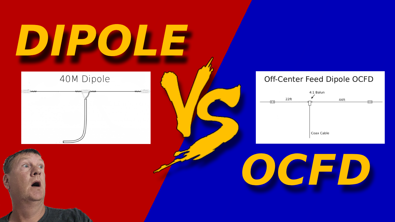
An off-center-fed dipole uses the same total wire length, but the feedpoint is moved away from the middle — often around 33–40% from one end. This shift pushes the feedpoint impedance up into the 200–300 Ω range (or higher on other bands), so you typically feed it through a 4:1 balun.
This off-center feed creates impedance points that are usable on multiple harmonically related bands. The OCFD is popular as a multiband HF wire antenna that covers several bands with a single feedline, often with little or no tuning on at least a few of them.
Quick Reference: Standard Dipole vs OCFD
| Property |
Standard Dipole |
OCFD |
| Feedpoint |
Center (50–75 Ω) |
Off-center (≈200–300 Ω) |
| Matching |
Often direct to 50 Ω |
Needs 4:1 balun (or more) |
| Multiband Use |
Limited without tuner or traps |
Good on multiple harmonics |
| Pattern Purity |
Clean, predictable |
More lobes and nulls |
| Best For |
Single-band, low-cost, training |
Compact multiband home station |
Design Differences
Both antennas look similar on a sketch, but small changes in feedpoint location and hardware make them behave very differently.
- Standard dipole: Two equal legs, center-fed, often uses a simple 1:1 current balun or choke at the feedpoint.
- OCFD: Two unequal legs, feedpoint shifted off center, most designs use a 4:1 current balun plus a choke to keep common-mode currents in check.
Because the OCFD feed impedance is higher and more variable across bands, the quality of the balun and choke matters more. A poorly built balun can add loss, heating, and RF-in-the-shack problems, especially at higher power.
Radiation Patterns
On its fundamental band, a horizontal half-wave dipole hung at a reasonable height has a classic broadside pattern: strongest off the sides, weaker off the ends. As you go up in frequency, additional lobes and nulls appear, but the pattern remains symmetric.
An OCFD shares the same total wire length, but the off-center feed adds asymmetry. You still get broadside gain on some bands, but the pattern can show skewed lobes and deeper nulls. On higher bands, you may notice strong “hot spots” in specific directions and dead zones in others.
- Dipole: Smooth, predictable pattern — great for learning and for consistent coverage in two broad directions.
- OCFD: More complex pattern, especially on higher bands — can be helpful or frustrating depending on your target directions.
In real life, trees, rooflines, and odd supports already distort patterns, so the differences may be less dramatic than perfect NEC plots. Still, if you rely on certain paths (for example, a favorite DX direction), pattern predictability can be a deciding factor.
Feed-Point Impedance & Matching Requirements
This is where the dipole vs OCFD comparison really becomes practical. It’s all about how hard your radio and tuner have to work to deliver power into the antenna system.
Standard Dipole Matching
A properly cut half-wave dipole at its design frequency will usually show an impedance near 50–75 Ω at the center. That’s naturally close to your 50 Ω coax and radio. Many operators run a dipole directly from the rig with no external tuner at all.
On harmonic bands, impedance rises and may become reactive. A tuner can often tame this, but you’re now outside the sweet spot where the antenna was intended to be resonant.
OCFD Matching
An OCFD, by design, moves the feedpoint to a spot where the impedance on several bands is “high but manageable.” One common feedpoint position is around 1/3 of the total length from one end. There, the impedance on the fundamental and several harmonics lands in the 200–300 Ω zone.
Feed that through a 4:1 current balun, and you’re closer to 50–75 Ω on multiple bands. Many OCFD designs provide reasonable SWR on at least three or four HF bands right out of the box, with a tuner cleaning up the remaining mismatch.
Matching Snapshot
- Standard dipole: Best match on a single band, simple tuner use on nearby bands.
- OCFD: Usable match on several bands with a 4:1 balun, tuner makes it more flexible.
- Key takeaway: Dipole = easier matching, OCFD = more bands from one wire.
Bandwidth & Multiband Behavior
On the fundamental band, a half-wave dipole offers a comfortable bandwidth where SWR stays low enough for most rigs. If you mostly live on one band — say 40 m or 20 m — a dipole cut for that band is hard to beat.
The OCFD shines when you want multiband coverage without separate antennas. Because of the off-center feed, the same wire length presents workable impedance on several harmonic bands. For example, a 40 m OCFD might also work on 20, 15, and 10 m with acceptable SWR.
| Design |
Fundamental Band |
Typical Usable Harmonics |
Notes |
| Standard 40 m Dipole |
40 m |
Some use on 15 m with tuner |
Best performance on 40 m; tuner needed on others |
| 40 m OCFD |
40 m |
20 m, 15 m, 10 m (often more) |
Multiband by design; tuner improves edge-of-band SWR |
Installation Flexibility
Most of us don’t have a contest station tower farm. You probably have trees, roof anchors, maybe a single mast, and a yard that’s smaller than your dreams. How do the antennas compare in the real world?
Standard Dipole Installation
- Needs a center support if you want a flat-top configuration.
- Works well as an inverted-V if you can only get the center high.
- Feedline usually drops from the center, which may be the most awkward point to reach.
OCFD Installation
- Feedpoint is off-center, so you can place it closer to your shack for shorter coax runs.
- One leg is longer than the other; this can help you “bend” the antenna around your lot.
- Still works well as an inverted-V or sloper, but leg lengths matter more for pattern and tuning.
If you have a convenient tree or mast near the house, an OCFD feedpoint mounted near that support can simplify everything. If your best support is dead-center in the yard, a classic dipole may be easier to hang.
Noise Performance
Noise is often more about your location and grounding than the exact wire layout, but the antenna design still has an effect.
- Dipole: Symmetrical feed and a good current balun help reject common-mode noise on the feedline.
- OCFD: Higher feedpoint impedance and asymmetry can make it more sensitive to common-mode currents if the balun and choke aren’t up to the job.
In practice, a well-choked OCFD can be nearly as quiet as a dipole. But if you rush the build or cheap out on the balun, you’re more likely to hear hash from switching supplies, routers, and TV sets riding in on the coax shield.
Efficiency & Power Handling
A straight dipole with a simple 1:1 current balun is very efficient. There’s not much to heat up or saturate. As long as your wire and connections are solid, it will happily run the full legal limit in most home stations.
An OCFD can also be efficient, but more things can go wrong. The balun sees higher voltages and currents on multiple bands, and it has to deal with different reactances. Poor core material, thin wire, or undersized enclosures can all lead to heating and loss.
- Dipole: Simple, robust, easy to run high power if built sensibly.
- OCFD: Good efficiency when built with quality cores and wire; balun becomes a critical component.
Use Cases & Best Applications
Choosing between a standard dipole vs OCFD is easier if you think about how you actually operate, not just what looks good on a diagram.
When a Standard Dipole Is the Better Choice
- You’re learning HF and want the simplest, most predictable antenna.
- You mainly operate on one band (for example, 40 m during the evening or 20 m during the day).
- You want a low-cost, low-complexity antenna with high efficiency and no surprises.
When an OCFD Is the Better Choice
- You need multiband coverage from a single wire and feedline.
- Your yard or roof layout makes an off-center feedpoint more convenient.
- You’re comfortable with baluns, common-mode chokes, and the idea of occasional antenna analyzer sessions.
Pros and Cons Table
| Feature |
Standard Dipole — Pros |
Standard Dipole — Cons |
OCFD — Pros |
OCFD — Cons |
| Complexity |
Very simple build and match |
Less flexible across many bands |
Still relatively simple wire layout |
Balun choice and quality matter a lot |
| Multiband Operation |
Best on one band |
Tuner or traps needed for others |
Good on several bands with one antenna |
Not always perfect on every advertised band |
| Radiation Pattern |
Clean, predictable broadside lobes |
Less directional flexibility on harmonics |
Multiple lobes can favor DX paths |
Deep nulls and pattern quirks possible |
| Noise |
Often quieter with a good choke |
Can still pick up local noise sources |
Similar noise if well-choked |
More prone to common-mode noise if not |
| Power Handling |
Excellent; few parts to overheat |
Mechanical strength still matters |
Capable of high power with good balun |
Poor balun design may heat or fail |
Testing & Real-World Performance Observations
So how do these antennas feel on the air? Reports from countless operators, plus simple A/B tests, paint a consistent picture if you keep the installations roughly comparable in height and orientation.
- On the fundamental band, the dipole and OCFD often sound very similar into broadside directions.
- On harmonic bands, the OCFD can show stronger signals in some directions and weaker in others due to its more complex pattern.
- When noise and local RFI are under control, both antennas can deliver excellent DX performance given enough height.
Simple S-Unit Comparison (Typical Reports)
| Scenario |
Standard Dipole |
OCFD |
Typical Comment |
| 40 m, broadside path |
S7 |
S7 |
“No real difference between them.” |
| 20 m, off-broadside path |
S6 |
S8 |
“OCFD seems hotter in that direction.” |
| 15 m, null direction |
S5 |
S3 or not heard |
“OCFD has a deep null right there.” |
| Noise level in a quiet suburb |
S3 |
S3–S4 |
“About the same when both are well-choked.” |
These numbers are just representative, but they show the theme: neither antenna is “magic.” The OCFD isn’t a beam, and the dipole isn’t useless above its fundamental. They’re both solid, proven HF wire antennas when installed thoughtfully.
Frequently Asked Questions
Is a standard dipole or an OCFD better for a beginner?
A standard half-wave dipole is the better starting point. It is simple to build, easy to match without a balun on its design band, and has a clean, predictable pattern. Once you understand how it behaves, an OCFD is a logical next step when you want multiband coverage from a single feedline.
Why does an OCFD need a 4:1 balun?
Moving the feedpoint off center pushes the impedance up to about 200 to 300 ohms on the design band, with similar high-impedance points on harmonically related bands. A 4:1 current balun transforms that to roughly 50 ohms so your radio sees a usable match. Without it, the SWR would be too high for direct coax feed.
How many bands does a typical OCFD cover?
Most off-the-shelf 80 meter OCFDs work reasonably well on 80, 40, 20, and 10 meters, and many also load on 17 and 6 meters with a tuner. The exact band coverage depends on the feedpoint offset and balun design. A standard center-fed 80 m dipole only resonates on 80 m without a tuner.
Which antenna is quieter in a noisy suburban environment?
When both antennas are well-built and properly choked against common-mode currents, the noise floor is similar. The OCFD can be slightly noisier on some bands because asymmetric currents on the feedline are easier to develop, which is why a good current balun and a separate choke at the radio end of the coax matter so much. A center-fed dipole with a 1:1 choke is a little more forgiving in this respect.
Can I use my OCFD without a tuner?
On its primary band, a well-tuned OCFD usually shows an SWR low enough that most modern radios will run full power without a tuner. On the higher harmonic bands the SWR is often workable but not perfect, so a built-in or external tuner makes life easier and helps stretch coverage across the wider portions of each band.
Does an OCFD have more gain than a regular dipole?
Not really. Both antennas have similar peak gain on their primary band. What changes is the radiation pattern: an OCFD has more lobes and deeper nulls on its harmonic bands, which can make it feel hotter in some directions and dead in others. Real on-air differences usually come from the pattern shape and antenna height, not raw gain.
Which One Should You Put In the Air?
When you strip away the myths, the dipole vs OCFD debate is less about "better or worse" and more about what you want your station to do. A standard half-wave dipole is the reliable workhorse: easy to build, easy to match, and very predictable on its primary band.
An off-center-fed dipole takes that same basic idea and bends it toward convenience. You give up some pattern purity and add dependence on a quality balun, but you gain multiband coverage from a single wire and feedline. For many home stations, that's a trade worth making.
If you're starting out, need a dependable emergency antenna, or just want a reference you can trust, begin with a standard dipole. Once you're comfortable and ready to simplify your antenna farm, experiment with an OCFD to see how it fits your operating style and local noise environment.
Next steps: explore more ham radio antenna articles, compare with vertical and end-fed designs, or dive into modeling and pattern plots to sharpen your understanding of how wire antennas really behave.
Where to Go Next