Tired of switching antennas every time you change bands? Fed up with antenna tuners that never quite get your SWR perfect? The Tilted Terminated Folded Dipole (T2FD) antenna might be the solution you've been searching for. This remarkable wideband antenna covers all HF frequencies from 3 to 30MHz with a single feedline, no tuning required. Here's how to build your own professional-grade T2FD antenna that delivers consistent performance across the entire HF spectrum.
Why the T2FD Antenna is Perfect for Modern Ham Radio
The T2FD antenna represents one of the most elegant solutions to the multi-band antenna challenge. Originally developed during World War II for military communications, this design offers several compelling advantages over traditional multi-band antennas:
- True wideband operation - Works on all HF bands without switching or tuning
- Consistent radiation pattern - Maintains similar characteristics across frequencies
- No trap circuits - Eliminates the losses and failure points of trap antennas
- Simple construction - Uses basic materials available at any hardware store
- Weather resistant - Non-resonant design is less affected by environmental changes
"I've used trap dipoles, fan dipoles, and automatic antenna tuners. Nothing comes close to the simplicity and reliability of my T2FD. It just works, on every band, every time."
Unlike resonant antennas that work efficiently on specific frequencies, the T2FD is a traveling-wave antenna. This fundamental difference allows it to maintain acceptable SWR across an extremely wide frequency range, making it ideal for modern digital modes, weak signal work, and emergency communications where band agility is crucial.
Materials Needed
Primary Components for T2FD Antenna:
Hardware Requirements:
- Stainless steel bolts and nuts for connections
- Waterproof enclosure for termination resistor
- Cable ties and electrical tape
- Coax connectors (PL-259 or N-type)
- Grounding hardware
Optional Upgrades:
- Copperweld antenna wire for improved durability
- 1:1 current balun for additional common-mode suppression
- Lightning arrestor for feed point protection
- Guy wire insulators for support rope
Tools Required
Essential Tools:
- Wire strippers and cutters
- Drill with bits for mounting hardware
- Soldering iron and 60/40 rosin-core solder
- Multimeter for continuity checking
- Measuring tape (at least 50 feet)
- Crimping tool for coax connectors
Helpful Tools:
- SWR analyzer for testing and tuning
- Antenna modeling software (EZNEC or 4NEC2)
- Cable pulling system for installation
- Ladder or tower access equipment
Safety Equipment:
- Safety harness and fall protection
- Hard hat and safety glasses
- Insulated tools for electrical work
- First aid kit for installation day
Understanding T2FD Theory and Dimensions
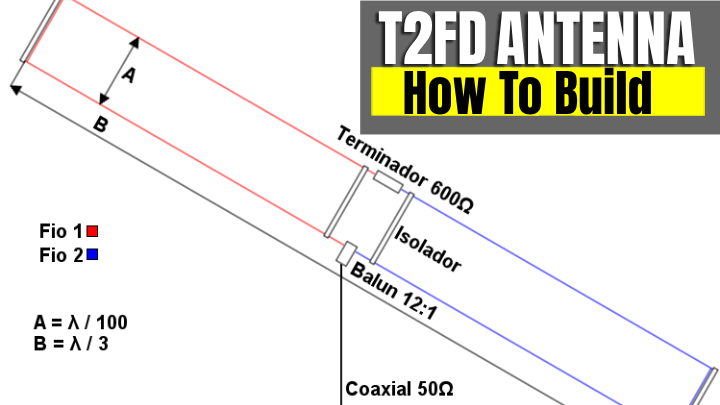
The T2FD antenna consists of two parallel wires forming a folded dipole, but unlike a traditional folded dipole, it includes several key differences that enable wideband operation:
T2FD Design Elements
- Tilted configuration - One wire is longer than the other
- Termination resistor - Absorbs reflected energy at far end
- Folded geometry - Creates impedance transformation
- Non-resonant operation - Traveling wave rather than standing wave
The dimensions for an all-band HF T2FD antenna are carefully calculated to provide optimal performance:
Top wire length: 135 feet
Bottom wire length: 131 feet
Wire separation: 6 feet
Total system length: 135 feet
Termination resistance: 800 ohms
These dimensions represent a compromise that works well across the HF spectrum. The 4-foot difference between wire lengths creates the "tilt" that gives the antenna its name, while the 800-ohm termination resistor provides proper impedance matching for the traveling wave.
Step 1: Calculate and Cut Wire Elements
Precision in wire cutting is critical for proper T2FD operation. Small errors in length can significantly affect performance, particularly on the higher HF bands.
Start by measuring and marking your wire lengths on a large, flat surface. A parking lot or gymnasium floor works well for this step. Use a measuring tape to mark each wire length, adding an extra 6 inches to each end for connections and adjustments.
⚠️ Critical Measurement Note
These measurements assume bare wire. If using insulated wire, add 2-3% to compensate for the velocity factor of the insulation. Always verify with an antenna analyzer after installation.
Wire Cutting Checklist:
- Top wire: 135 feet + 12 inches = 136 feet total
- Bottom wire: 131 feet + 12 inches = 132 feet total
- Mark connection points clearly with electrical tape
- Strip wire ends for mechanical connections
- Check continuity with multimeter before installation
Step 2: Prepare the Termination Resistor Assembly
The termination resistor is arguably the most critical component of the T2FD antenna. This resistor absorbs the energy that would otherwise reflect back along the antenna, maintaining the traveling wave characteristics essential for wideband operation.
Select a high-quality 800-ohm, 25-watt non-inductive resistor. Wirewound resistors should be avoided because their inductance can affect performance at higher frequencies. Carbon composition or metal film resistors work best for this application.
Termination Resistor Specifications
- Resistance: 800 ohms ±5%
- Power rating: 25 watts minimum
- Type: Non-inductive (carbon or metal film)
- Temperature coefficient: Low for stability
- Mounting: Suitable for outdoor use
Mount the resistor in a weatherproof enclosure with proper heat dissipation. The resistor will dissipate several watts during operation, so adequate ventilation is important. Use stainless steel hardware for all connections to prevent corrosion.
Step 3: Install Support Structure
The T2FD antenna requires a support structure that maintains the proper wire spacing and orientation. The antenna should be installed as high as possible for best performance, with the wires parallel to the ground.
You have several options for support structures:
- Two towers or poles - Ideal for permanent installation
- Trees with pulleys - Good for temporary or stealth installations
- Single support with guy wires - Compact option for smaller lots
- Inverted-V configuration - Alternative for limited space
The key requirement is maintaining the 6-foot spacing between wires throughout the antenna length. Use spreaders every 20-25 feet to prevent the wires from touching during wind or ice loading.
Recommended installation height: 35-50 feet
Minimum installation height: 20 feet
Wire spacing tolerance: ±6 inches
Maximum sag: 2 feet at center
Step 4: Connect the Feed Point
The T2FD feed point uses a 4:1 current balun to transform the antenna's nominal 200-ohm impedance to 50 ohms for your coax feedline. This balun also provides common-mode rejection, reducing RF in the shack and improving antenna performance.
Install the balun at the point where the two wires connect, typically at one end of the antenna system. Use a high-quality current balun designed for the power levels you plan to operate. Many commercial baluns are rated for 1500 watts or more, providing adequate headroom for legal limit operation.
Feed Point Connection Steps:
- Strip wire ends and tin with solder
- Connect top wire to balun's top terminal
- Connect bottom wire to balun's bottom terminal
- Attach coax shield to balun ground
- Connect coax center conductor to balun output
- Seal all connections with self-amalgamating tape
- Support balun to prevent stress on connections
Step 5: Install and Connect Termination Resistor
At the far end of the antenna, install the termination resistor between the two wires. This connection must be secure and weatherproof, as any degradation will affect antenna performance across all bands.
The termination resistor assembly should be mounted in a weatherproof enclosure with adequate ventilation. Some builders use a short length of PVC pipe with end caps, drilling ventilation holes and sealing them with mesh to prevent insect entry.
⚠️ Power Handling Consideration
The termination resistor typically dissipates 25-30% of your transmitter power. At 100 watts output, expect 25-30 watts of heat dissipation. Ensure adequate cooling and use resistors rated for at least twice the expected power.
Use stainless steel hardware for all connections to prevent corrosion. Apply a thin coat of antioxidant compound to copper connections before assembly. This prevents galvanic corrosion and ensures long-term reliability.
Step 6: System Grounding and Lightning Protection
Proper grounding is essential for both safety and performance. The T2FD antenna system should be connected to your station's RF ground system through the coax shield and balun case.
Install a lightning arrestor at the point where the coax enters your building. This provides protection for your equipment while maintaining the RF characteristics of the feedline. Use high-quality gas discharge arrestors rated for your power levels.
- Ground rod installation - Minimum 8-foot copper-clad steel rod
- Ground wire sizing - #6 AWG minimum for lightning protection
- Arrestor specifications - Gas discharge type, appropriate power rating
- Building entry - Seal penetrations to prevent water entry
Testing and Verification
Once installation is complete, comprehensive testing ensures optimal performance. Start with basic continuity checks using a multimeter, then proceed to SWR measurements across the HF spectrum.
T2FD Testing Procedure:
- Continuity test: Verify all connections with multimeter
- Resistance check: Measure termination resistor value
- SWR sweep: Test SWR from 3-30 MHz
- Power test: Start with low power, increase gradually
- Pattern verification: Compare signal reports with expectations
Expected SWR readings for a properly constructed T2FD antenna:
| Frequency Band |
Expected SWR |
Performance Notes |
| 80 Meters |
2.5:1 - 3:1 |
Acceptable for most transceivers |
| 40 Meters |
2:1 - 2.5:1 |
Good performance across band |
| 20 Meters |
1.5:1 - 2:1 |
Excellent match |
| 15 Meters |
2:1 - 2.5:1 |
Good performance |
| 10 Meters |
2.5:1 - 3:1 |
Acceptable match |
If SWR readings are significantly higher than expected, check for loose connections, damaged wire, or improper termination resistor values. Small adjustments to wire length may be necessary to optimize performance for your specific installation.
Performance Optimization and Troubleshooting
Fine-tuning your T2FD antenna involves making small adjustments to optimize performance across your preferred operating frequencies. Unlike resonant antennas, the T2FD responds to changes differently, requiring a systematic approach to optimization.
Common Issues and Solutions:
- High SWR on all bands: Check termination resistor value and connections
- Poor low-band performance: Verify wire lengths and spacing
- Intermittent operation: Inspect for corroded connections or broken wires
- RF in the shack: Add 1:1 current balun at feedline entry point
- Weather sensitivity: Ensure proper drainage and wire tensioning
The T2FD's performance can be affected by nearby metal objects, buildings, and other antennas. Try to maintain at least one wavelength separation from other antennas at the lowest operating frequency. This prevents interaction that can degrade performance on multiple antenna systems.
Results and Performance Expectations
A properly constructed T2FD antenna delivers consistent performance across the HF spectrum. While it may not match the peak performance of optimized monoband antennas, its convenience and reliability make it an excellent choice for many applications.
Typical Performance Characteristics:
- Gain: 0 to +3 dBi depending on frequency and height
- Front-to-back ratio: Modest directivity, primarily broadside
- Radiation angle: Low angle for DX, varies with height
- Bandwidth: Useful coverage from 3.5 to 30 MHz
- Power handling: Limited by termination resistor (typically 100-400W)
The T2FD excels in applications where band agility is more important than maximum gain. Digital mode operators particularly appreciate the ability to switch frequencies without retuning, while emergency communicators value the reliability and consistent performance.
"During Field Day, while other stations were switching antennas and adjusting tuners, I was making contacts. The T2FD just works, and that reliability is worth more than a few dB of gain."
Maintenance and Long-Term Care
The T2FD antenna requires minimal maintenance compared to multi-element or trapped antennas. The simple design has fewer failure points and is generally more tolerant of weather-related stress.
Annual Maintenance Schedule:
- Visual inspection: Check for broken wires, loose connections, or corrosion
- SWR verification: Test across all bands to detect degradation
- Connection tightening: Ensure all mechanical connections remain secure
- Weather sealing: Renew tape and sealant on exposed connections
- Support structure: Inspect guys, pulleys, and mounting hardware
The termination resistor should be inspected periodically for signs of overheating or moisture intrusion. Carbon composition resistors can drift over time, so checking the resistance value every few years ensures continued optimal performance.
Frequently Asked Questions
What does T2FD stand for and how is it different from a normal dipole?
T2FD stands for Tilted Terminated Folded Dipole. Unlike a regular resonant dipole, the T2FD is a traveling-wave antenna with a non-inductive termination resistor at one end that absorbs the energy that would otherwise reflect back. That termination is what makes the antenna act broadband from roughly 3 to 30 MHz instead of being sharp on a single band.
Do I need an antenna tuner with a T2FD?
Often no. A well-built T2FD typically holds SWR in the 1.5:1 to 3:1 range across all HF bands, which most modern transceivers handle without protection cutbacks. A wide-range tuner is still useful for cleaning up edge bands and matching older rigs, but unlike a resonant dipole, the T2FD does not depend on a tuner to operate across the spectrum.
How much power does the termination resistor need to handle?
About one-third of your transmitter power is dissipated in the termination resistor, so a 25 W non-inductive resistor is comfortable for a 100 W rig. If you plan to run an amplifier or sustained digital modes, step the resistor up accordingly. Use a non-inductive type rated for the actual continuous power, mounted in a weatherproof enclosure with airflow.
How long does the T2FD have to be?
A common military-style design uses a 135 ft top wire, a 131 ft bottom wire, and roughly 6 ft of vertical spacing between them, which gives broadband HF coverage from about 3 to 30 MHz. You can scale the design down for higher minimum frequencies, but shorter T2FDs lose low-band performance and start to behave more like an aperiodic short antenna.
Can a T2FD be used for transmit on all HF bands?
Yes. Properly built, a T2FD will transmit cleanly across the entire HF spectrum. You give up some peak gain compared to a resonant antenna on a specific band, but you gain consistent SWR and pattern from 80m through 10m on a single feedline. That trade-off is exactly why T2FDs are popular for emergency communications, digital modes, and SWL stations.
What feedline and balun should I use with a T2FD?
Feed the antenna through a 4:1 current balun rated for HF and the power level you plan to run. Use 50 ohm coax such as RG-8X for short runs or RG-213 / LMR-400 for longer permanent installations. Add a 1:1 common-mode choke at the entry to the shack to keep RF off the coax shield.
Conclusion: Embrace Wideband Simplicity
Building a T2FD antenna represents a step toward operational simplicity without sacrificing capability. This antenna design eliminates the complexity of antenna switching, reduces the likelihood of SWR-related equipment damage, and provides reliable performance across the entire HF spectrum.
The T2FD isn't perfect—no antenna is. It sacrifices some peak gain for incredible convenience and bandwidth. For many amateur radio operators, this trade-off makes perfect sense. Contest stations may need the last dB of gain, but for everyday operation, emergency communications, and digital modes, the T2FD delivers excellent value.
The construction techniques outlined here will result in a professional-quality antenna that provides years of reliable service. Unlike complex beam antennas or finicky trap designs, the T2FD forgives minor construction errors and operates consistently across a wide range of environmental conditions.
Most importantly, the T2FD antenna gets you on the air and keeps you there. While others are adjusting tuners and switching antennas, you'll be making contacts. Sometimes, the best antenna is simply the one that works reliably every time you key up.