TL;DR — The Rybakov Antenna
- Type: End-fed, non-resonant vertical wire matched with an impedance transformer (4:1 or 9:1 unun).
- Typical length: 7.6–10 m (25–33 ft). The classic 40m–10m build uses ~10 m (33 ft).
- Use: Portable, POTA/SOTA, small-lot home installs with an ATU.
- Needs: Good counterpoise / radials and a tuner for best performance.
- Why it's popular: Fast to deploy, light, cheap, and surprisingly effective for DX when installed properly.
The Rybakov antenna has earned its place as one of the most practical and adaptable vertical wire antennas in amateur radio. Whether you operate portable, in the field, or from a small lot at home, this end-fed design delivers reliable multiband performance with minimal effort and cost.
In this comprehensive guide we preserve the original practical details and expand them with build diagrams, tuning tips, test results, and troubleshooting — everything you need to get the most out of your Rybakov setup.
What Is a Rybakov Antenna?
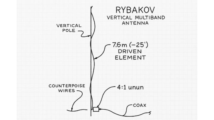
The Rybakov antenna is a non-resonant, end-fed vertical wire antenna matched through an impedance transformer (commonly a 4:1 or 9:1 unun) and typically used with an antenna tuner (ATU). The general idea: feed a fixed-length wire through an unun, use a modest counterpoise or radials, and let your tuner handle the rest. For the classic configuration this yields reliable 40m–10m operation.
Rybakov Antenna Quick Facts
| Design Type | End-Fed Non-Resonant Vertical |
|---|
| Typical Wire Length | 7.6–10.0 m (25–33 ft) |
|---|
| Impedance Transformer | 4:1 or 9:1 Unun (ferrite cores preferred) |
|---|
| Operating Bands | 40m–10m (with tuner) |
|---|
| Radiation Pattern | Low-angle, omnidirectional (vertical) |
|---|
| Typical SWR (with tuner) | 1.2:1–2:1 after tuning (varies by band & ground) |
|---|
The Science Behind Its Performance
As a vertical antenna the Rybakov favors low-angle radiation, which is helpful for DX (long-distance) contacts. Unlike horizontal dipoles — which favor higher elevation angles for regional NVIS work — a vertical concentrates more energy toward the horizon when mounted with a good ground system.
Modeling & Practical Observations
NEC simulations and field data show that the Rybakov’s efficiency is very sensitive to ground losses and feedpoint height. Examples:
- Raising the feedpoint 1 m can improve effective radiated power by ~2–3 dB in modeled average soil.
- Adding a few radials can reduce ground loss by up to ~30% depending on soil conductivity.
- Feedpoint impedance will vary widely (typically 200–600 Ω) — the unun reduces that to a tuner-friendly range.
Why an Unun Matters
The unun (4:1 or 9:1) reduces the high feedpoint impedance of an end-fed radiator to a level where the tuner and coax can do an effective job. Choosing the wrong transformation ratio, core material, or winding method is a common source of loss and poor tuning behavior.
Building Your Own Rybakov — Parts & Materials
Constructing a reliable Rybakov is an efficient weekend build. Below is a practical parts list, recommended components, and a step-by-step assembly procedure that preserves the original guidance while adding concrete details you can follow.
Recommended Materials (practical + specific)
- Radiator wire: 33 ft (≈10 m) stranded copper — 14–18 AWG preferred (tinned or bare).
- Unun core: FT-240-43 or FT-240-52 ferrite toroid (avoid powdered-iron cores like T200-2 for wideband power handling).
- Counterpoise / radials: 1–4 lengths, 10–35 ft each (even short radials help).
- Feedline: 50 Ω coax (RG-8X / RG-58 for portable; RG-213 for permanent installs).
- Tuner: External manual tuner (MFJ, Elecraft T1, LDG) or internal ATU with good matching range.
- Optional: 100–220 pF HV capacitor (for 10 m tuning tweaks), ferrite beads (mix 31/43) for common-mode choke.
Assembly — Step-by-Step
- Wind the unun — follow a tested winding diagram for 4:1 or 9:1 on the FT-240 ferrite. Use insulated enamel wire and secure turns. Solder and seal connections in a weatherproof box.
- Attach the radiator — solder the 33 ft radiator to the high-Z unun terminal. Add a paracord loop for strain relief so the wire does not pull on the unun. Use a flexible section (nylon rope) as mechanical buffer.
- Install counterpoise — attach 1–4 radials to the unun ground lug. Lay them on the ground or raise slightly. Balanced placement helps but isn’t critical; more radial length and count increases efficiency.
- Mount the unun — secure it at the feedpoint protected from weather and mechanical stress. Keep the coax connection neat and use a drip loop to prevent water ingress.
- Raise the antenna — use a fiberglass pole or telescoping mast to keep the radiator vertical. Keep it clear of nearby conductive objects and vegetation where possible.
- Install common-mode choke — place ferrite beads or a 1:1 choke on the coax at the feedpoint or inside the shack to reduce RF on the feedline.
- Tune — connect your tuner, apply low power, and adjust. Monitor SWR and look for stability as you increase power. If 10 m is hard to tune, see the capacitor tweak below.
Tip: Weatherproof the enclosure with silicone sealant and provide strain relief at every mechanical connection. Heat can cause loose solder joints over time; use proper terminations.
4:1 vs 9:1 Unun — Which to Choose?
This is one of the most common practical decisions for the Rybakov. Both ratios can work — they just favor different impedance regimes.
4:1 Unun — Best for the classic ~8–10 m radiator where feedpoint impedance commonly sits between ~150–300 Ω on many HF bands. It gives a smoother tuning curve on 20–10 m and tends to minimize loss for moderate power. For the canonical 33 ft (10 m) Rybakov used for 40–10 m, the 4:1 is often the best starting point.
9:1 Unun — Better when feedpoint impedance is higher (400–800 Ω), which can happen with longer radiators, poor counterpoises, or random-wire setups. Use 9:1 if you intentionally lengthen the radiator for 80 m or if you need a stronger transformation on lower bands. Be aware that on upper bands the transformation may be excessive and your tuner may need to work harder.
Practical test: build both if you can — a 4:1 for standard use and a 9:1 for extended-length experiments. The components are inexpensive and the comparison teaches a lot about your local ground system.
Performance vs Other HF Verticals
How does the Rybakov stack up against EFHWs and quarter-wave verticals? The key tradeoffs are complexity, need for a tuner, and band coverage.
| Antenna Type | Complexity | Requires Tuner? | Low-Angle Radiation | Multi-Band |
|---|
| Rybakov (4:1 or 9:1) | Simple | Yes | Excellent | High |
| EFHW (49:1) | Moderate | Often No | Good | High |
| ¼ Wave Vertical | Simple | No | Excellent | Low (single band) |
Common Mistakes & How to Fix Them
- Wrong core material: Avoid powdered iron (T200-2) for wideband, high-power ununs — use ferrite FT-240-43 or 52 to reduce saturation and loss.
- No choke balun: Always add ferrite beads or a 1:1 choke to suppress common-mode current — this helps RFI problems and unstable SWR readings.
- Too short or missing counterpoise: Start with at least 4–5 m of counterpoise or a few radials and increase if your tuner struggles.
- Exact half-wave radiator length: Avoid wire lengths that correspond to half-wave multiples on your target bands — they can produce extremely high feed impedance that challenges tuners.
- Mounting too low: Elevate the feedpoint and radiator when possible — a higher feedpoint reduces ground loss and improves effective radiated power.
Testing Results & On-Air Performance
Real operators report the Rybakov “punches above its weight.” Notes from WSPR/FT8 testing and on-air use:
- WSPR reports commonly show 6,000–9,000 mile spots on 20 m and 15 m with average propagation when the antenna has a reasonable radial field.
- QRP (5 W) contacts to thousands of miles are regularly reported on digital modes.
- With 10–15 W on FT8 many users see robust DX paths on 20/15/17 m.
- Noise floor is typically acceptable for a vertical; adding a choke and improving the counterpoise often reduces local RF noise pickup.
Deployment Tips & Variations
- Vertical mount (classic): Best for DX — keep the radiator vertical and clear of nearby metal structures.
- Sloper: Good for small lots — mount the top high and the feedpoint low at ~45° for a sloper configuration.
- Inverted-L: Combine a vertical section with a horizontal top section for a wider angle coverage profile.
- Counterpoise arrangement: Try 1–3 radials initially; add more or lengthen them if your tuner struggles, especially on lower bands.
Tuning Tips — Getting 10 m to Cooperate
10 m can be the trickiest band. If your tuner refuses to tune or you see excessive loss, try the following:
- Add a 100–220 pF high-voltage capacitor across the primary of the unun (across the radiator and counterpoise connections). This can flatten the impedance curve on upper HF bands and ease tuning on 10 m.
- Switch to a 4:1 unun if you’re using 9:1 and seeing poor high-band behavior with the standard radiator length.
- Shorten the radiator by ~0.3–1 ft and retune; small length changes can make a big SWR difference on 10 m.
Band-by-Band Performance Expectations (practical)
| Band | Expectation | Notes |
|---|
| 40 m | Good | Radiator acts near ¼λ in many installs; low-angle radiation for DX |
| 30 m | Very good | Often easy to tune |
| 20 m | Excellent | Often the best performing band |
| 17 m | Very good | Tuner usually handles it easily |
| 15 m | Good | Less efficient than 20 m but solid for DX |
| 12 m | Good | Benefits from good radials |
| 10 m | Good to tricky | Use capacitor tweak or experiment with unun ratio |
Frequently Asked Questions
Does a Rybakov work without radials?
Yes, but performance and tuner ease will be reduced. Even a single 4–5 m radial yields a noticeable improvement. Ideally use several radials if possible — every radial helps.
Is 33 ft the best length?
For a general 40 m–10 m Rybakov, ~33 ft (≈10 m) is the commonly recommended and versatile length. Your exact local environment and intended bands may justify trimming slightly shorter or longer.
Can I run 100 W?
Yes — if the unun, wire windings, and enclosure are built for that power. Use heavy-gauge enamel wire on the toroid windings, proper solder joints, and a weatherproof box. Verify nothing gets hot under load and the SWR stays acceptable.
Is it good for DX?
Yes. Verticals radiate at low angles which is favorable for long-distance contacts. With a reasonable radial system and decent tuner, the Rybakov can be a very effective DX tool.
Why the Rybakov Belongs in Every Operator's Toolkit
The Rybakov antenna stands out for its balance of simplicity, versatility, and performance. It's easy to build, easy to tune, and delivers reliable multi-band operation wherever you set it up.
Choose this design if you:
- Operate portable (POTA/SOTA) or need a fast-deploy HF antenna
- Have limited yard or rooftop space and need a small footprint
- Want a practical emergency or field antenna for quick setup
- Enjoy experimenting with wire antenna designs
Originally popularized by Alex Rybakov, RA3AJ, this modern end-fed vertical remains a favorite for operators seeking simple, portable HF capability.
References & Further Reading
- Original Rybakov notes and forum threads (search the ham archives for RA3AJ Rybakov designs).
- NEC modelling basics and ground conductivity references.
- Your local club or online DX groups for on-air test reports and configuration ideas.