A vertical dipole array, or VDA, is one of those antennas that seems almost unfair when you get it right: two simple vertical dipoles on a fiberglass mast that suddenly make the bands sound bigger, cleaner, and a lot more one-way. This guide walks you through planning, building, and tuning a two-element VDA for HF DX, with a focus on portable use from beaches and saltwater locations.
If you’re comfortable with cutting dipoles, tying guy ropes, and trimming for SWR, you already have most of the skills needed to build a VDA. The tricks are in the geometry and in using the shoreline to your advantage, not exotic parts or black magic matching networks.
We’ll focus on a two-element VDA for bands like 20, 17, or 15 meters. You can scale the same ideas to 12 and 10 meters or adapt them for other bands, but it’s best to nail one band first, collect some DX, then clone the design. If you’re brand new to HF antennas, it may help to skim the main Antennas section on Broken Signal first so the basics feel familiar.
How a vertical dipole array actually works
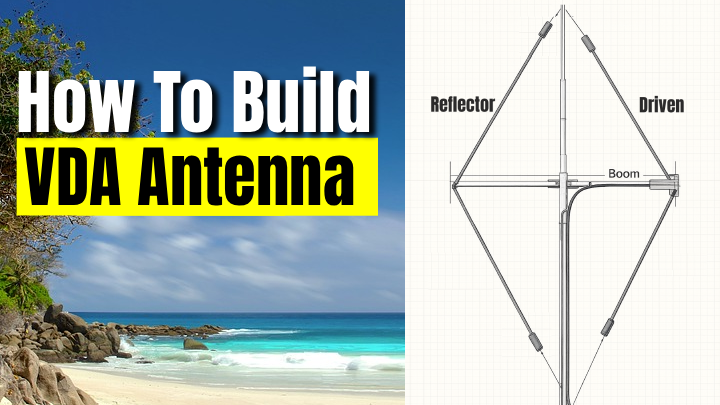
A single vertical dipole over good ground already has a fairly low takeoff angle. When you add a second element a fraction of a wavelength in front or behind and get the spacing right, the pair behaves like a compact end-fire beam. The pattern has a broad forward lobe, deep null off the back, and a low angle of maximum radiation that lines up nicely with the way HF signals arrive over long paths.
The magic ingredient with a VDA isn’t just geometry, though. Salt water is a nearly perfect ground at HF, which sharpens the low-angle lobe and adds a little “free” gain in the direction the array is facing. That’s why VDAs became so popular on island DXpeditions where you can stand the mast right at the edge of the beach and fire the main lobe over open ocean.
Typical single-band VDA design numbers
| Metric |
Typical Value (20 m band) |
Why It Matters |
| Element spacing (driven to reflector) |
About 0.25 λ (3.5 m on 20 m) |
Sets the forward gain and front-to-back ratio of the array. |
| Height of boom above sand |
About 0.4 λ (around 6 m on 20 m) |
Keeps the current maximum well above ground, helping low-angle radiation. |
| Forward gain over a single vertical |
Roughly +3 to +5 dB |
Equivalent to nearly one S-unit at the far end of the path. |
| Front-to-back ratio |
20–25 dB when tuned well |
Knocks down noise and QRM from behind the antenna. |
Materials, tools, and quick build overview
Before you start cutting wire, it helps to think of the VDA as three main assemblies: a fiberglass mast, a lightweight cross-boom that holds the two vertical dipoles, and the wire elements themselves. Build each piece so it can travel easily, then put them together in just a few minutes once you’re on site.
Recommended materials
- One 10–12 m fiberglass mast (Spiderbeam-style or similar, non-conductive).
- Non-conductive boom or cross-arm about one wavelength long (PVC, fiberglass tube, or lightweight wood sealed from moisture).
- Insulated copper antenna wire (AWG 18 or similar) for the driven and reflector elements.
- Strong UV-resistant rope for guying and for tying the element ends back to the mast.
- End insulators and a center insulator for the driven element feedpoint.
- 50 ohm coaxial cable (RG-8X, LMR-240, or similar) with a good ferrite choke at the feedpoint.
- Tent stakes or screw-in anchors to hold guys in sand or soft ground.
- Optional: weatherproof junction box to protect the feedpoint and choke.
Useful tools
- Antenna analyzer or at least an SWR bridge and HF rig with low power setting.
- Measuring tape, marker, and small notebook for recording trim changes.
- Side cutters, knife, and crimp tool or soldering iron for wire and coax.
- Drill and small hardware (bolts, washers, nuts) for attaching boom to mast.
Quick build steps at a glance
- Step 1: Pick your band and operating spot near salt water, with a clear shot toward your target DX area.
- Step 2: Cut the driven and reflector vertical dipole elements slightly long, based on the chosen band.
- Step 3: Build or adapt a non-conductive boom, then attach it to your mast at the proper height.
- Step 4: Hang both vertical elements from the boom, spaced correctly along its length.
- Step 5: Connect the feedpoint and choke, then trim and test until SWR and pattern look good.
Planning your VDA for a specific band
Most people start with 20 m, 17 m, or 15 m, because the mast and wire lengths are manageable and saltwater enhancement is obvious. You can absolutely build a 12 m or 10 m version too, which is handy when conditions are hot and the band is full of short-skip and long-path DX. Stick with one band per array so you’re not fighting traps or complicated switching when you should be working pileups.
The table below gives ballpark physical dimensions for a single-band VDA built with typical insulated wire. These are starting values; you’ll still trim the driven element on site. The reflector is slightly longer to provide the necessary phase shift and rear null.
Starting dimensions for common VDA bands (insulated wire)
| Band |
Driven element length |
Reflector length |
Element spacing |
Boom height above sand |
| 20 m |
≈ 9.9 m |
≈ 10.4 m |
≈ 3.5 m |
≈ 6.2 m |
| 17 m |
≈ 7.7 m |
≈ 8.2 m |
≈ 2.8 m |
≈ 4.8 m |
| 15 m |
≈ 6.6 m |
≈ 7.0 m |
≈ 2.4 m |
≈ 4.4 m |
These lengths assume common stranded copper antenna wire and a velocity factor a bit under 1.0. If your wire insulation is thick or unusual, cut an extra few percent long and plan to trim more on site.
Step-by-step: building and erecting the array
Once you’ve settled on a band and rough dimensions, the rest is mostly careful measuring and neat mechanical work. Take your time with the build at home so that the actual deployment on a windy or hot beach is as quick and boring as possible.
-
Lay out and cut the vertical elements.
Mark the driven element length on your wire and cut it 2–3% longer than the target value from the table. Do the same for the reflector. Fold small “tuning tails” at the bottom of each leg so you can make fine adjustments later without re-terminating hardware.
-
Build the center insulator and feedpoint.
Use a stout plastic or fiberglass plate for the driven element center. Bring the two legs of the vertical dipole to ring terminals or a small barrier strip, then attach your 50 ohm coax. Keep the connections short and neat, and seal them later with self-amalgamating tape or liquid electrical tape.
-
Add a coax choke at the feedpoint.
To keep common-mode current off the outside of the feedline, wind several turns of coax through ferrite cores or make a compact coax loop near the feedpoint. Tie this to the mast so the weight doesn’t stress the driven element.
-
Prepare the boom and attachment points.
Decide which direction will be “forward.” Mark the center of the boom, then mark the driven element position slightly off center and the reflector position behind it. Drill small holes for rope or use clamp hardware so each element can hang freely and remain vertical.
-
Attach the boom to the mast.
The boom should sit roughly at the heights in the table for your band. On a telescoping fiberglass mast, that often means just above the halfway point. Strap or bolt the boom so it’s square to the mast and doesn’t twist when the wind kicks up.
-
Guy the mast before hanging elements.
Stand the mast with temporary guys, then adjust tension so it’s vertical with a little give for gusts. Use at least three guy points, and keep them out of the main lobe direction as much as practical.
-
Hang the reflector and driven elements.
Start with the reflector on the “back” side of the boom. Tie the top of each vertical dipole leg to the boom using short lengths of rope, then tie the bottom of each leg back toward the mast or to short stakes so the wire hangs nearly straight. Repeat for the driven element in front of it.
-
Dress the coax and final guying.
Route the coax straight down the mast for at least a couple of meters before letting it curve away toward the shack. Tighten guy ropes so the boom stays level and the elements stay vertical, then double-check knots and anchors.
-
Initial tuning with an analyzer.
Connect an analyzer at the end of the feedline and look for the SWR dip. If resonance is below your target frequency, trim a bit from both legs of the driven element. If it’s above, you cut too much; add wire back using the tuning tails. Aim for a clean dip where you’ll spend most of your time operating.
-
Pattern check and fine-tuning.
With a few known stations or beacons on the band, compare signal levels with the array pointed toward and away from them. A good VDA shows a clear front-to-back difference. Small tweaks to reflector length and spacing can sharpen the null if you’re patient.
VDA vs other portable DX antennas
So why go to the trouble of two elements on a mast when you could just stab a single vertical in the sand and get on the air? The answer depends on how much you care about forward gain, rear rejection, and how much of your operating actually happens from saltwater locations.
-
A single vertical with radials is quick, forgiving, and works anywhere, but it doesn’t give you the same deep rear null or extra punch in one direction that a VDA offers when it’s sitting in wet sand.
-
A small Yagi on a push-up mast can match or beat a VDA in free space but is often heavier, more wind-sensitive, and harder to erect safely right at the water line.
-
A delta loop or other wire beam is a nice alternative when you can’t get close to salt water. On a true beach, though, the vertical polarization of a VDA wins for low-angle DX, especially on the higher HF bands.
What performance to expect from a beach VDA
On a good beach with the boom close to the water’s edge and the lobe aimed over open sea, most operators report that a VDA consistently hears and works stations that are marginal on a simple vertical or random wire. The extra few dB of forward gain and the low angle of maximum radiation show up as stronger, steadier DX signals rather than dramatic S-meter swings.
The rear null is just as important. When you’re on a small island or a busy coastline, rotating the array so that houses and local noise sources are behind it makes the band sound cleaner. It also helps reduce interaction between stations if you’re running multiple positions on a DXpedition. Just remember that performance drops quickly as you move the array inland, so if you’re forced to set up 50–100 m back from the water, manage expectations and treat the VDA more like a basic two-element vertical array.
Practical tips, safety, and operating habits
Building a VDA isn’t hard, but there are plenty of small decisions that separate a pleasant evening on the beach from a broken mast and a pile of salty wire. A little overbuilding and some common-sense safety planning go a long way.
-
Respect wind and weather.
Fiberglass masts bend, but they do break. Use generous guy angles, don’t overtighten, and be willing to lower the array if gusts pick up or a storm rolls in.
-
Watch for power lines and people.
Never put a vertical array under or near power lines. On public beaches, keep the guys and wires obvious and out of walkways so no one trips or tangles in your setup.
-
Protect hardware from corrosion.
Salt air is brutal. Use stainless hardware where you can, rinse gear with fresh water after a long trip, and keep an eye on insulators and rope that sit in the sun all day.
For a more general overview of station planning and safety, the main Radio Articles section and the Getting Started guide on Broken Signal are worth a look, especially if you’re mixing a VDA with other antennas or running more than one transmitter.
Frequently Asked Questions
Do I need a tuner with a single-band VDA?
If you trim the driven element carefully, you can usually get SWR below 1.5:1 across a useful chunk of the band. A tuner is handy if you want to stretch the antenna a bit higher or lower than its sweet spot, but it shouldn't be required for normal operation around your design frequency.
Can I add more elements to make the array stronger?
In theory you can build three- or four-element vertical arrays, but the mechanical complexity and interaction with the shoreline make them much harder to tame in the field. For most portable use, a well-built two-element VDA is the sweet spot between gain, simplicity, and setup time.
What about multiband VDAs with traps or switching?
Traps and switching networks are possible, but every extra bit of hardware adds loss and one more failure point in a salty, sandy environment. Many DXpeditions bring separate VDAs for different bands instead. Once you've built one that works, cloning it for another band is straightforward.
How close is "close enough" to the water?
If you can put the mast at the top of the wet sand line or just behind it, you're in great shape. Ten or twenty meters back is usually still fine if the ground is saturated. Once you're well inland on dry soil, the VDA turns into a more ordinary vertical array and you lose most of the saltwater bonus.
Is a Vertical Dipole Array Right for Your Station?
If your idea of fun includes hauling a small station to the coast, catching the gray line, and punching above your weight on the higher HF bands, a vertical dipole array is absolutely worth the effort. It turns a simple portable setup into a directional DX tool that plays very well with salt water.
- A VDA shines when it's close to the shoreline with the main lobe aimed over open ocean.
- The build is within reach of anyone who can handle a basic wire dipole and a push-up mast.
- Careful tuning, good guying, and a solid choke at the feedpoint separate good arrays from frustrating ones.
Build one, take notes, and refine your design; after a few evenings of comparing it to simpler antennas, you'll know exactly when to grab the VDA for your next beach activation or DXpedition.