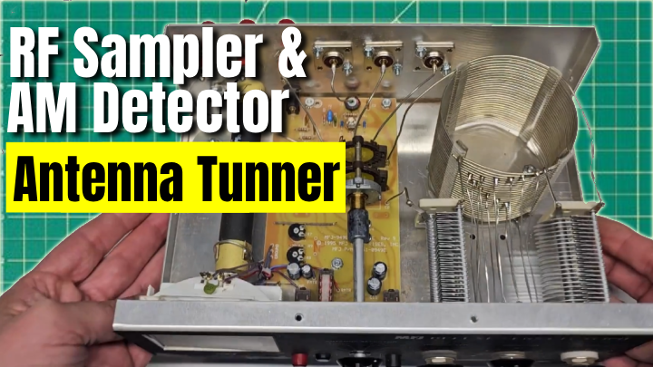
If you are building out a small RF workbench, the MFJ Deluxe Versa Tuner makes a handy hub. It already gives you a tuner and internal dummy load. By adding a simple RF sampler and AM detector right at the transceiver connector, you can plug in a scope or spectrum analyzer and actually see what your rig is doing without constantly breaking the line or risking your test gear.
The mod in this project uses two bulkhead SMA connectors mounted under the transceiver SO 239, one fed by a resistive RF sampler and the other by a simple 1N34A detector circuit. Both are built point to point and tied into existing chassis ground points, so you do not have to design a new PCB or gut the tuner.
With the RF sampler connected to a spectrum analyzer you can check output power, spurs, and harmonics. Plug the AM detector output into your scope and you can see the modulation envelope in real time while the tuner is feeding your antenna or the built in dummy load. It turns a plain tuner into the center of a small RF lab.
Why add an RF sampler and AM detector to a tuner?
Most of us do some amount of troubleshooting and alignment directly at the operating position. The MFJ Deluxe Versa Tuner already routes RF between the rig, antenna, and dummy load, so it is a natural place to grab a sample. By putting the sampler right behind the transceiver jack you always see what the radio is feeding into the tuner, regardless of which antenna or load is selected.
The AM detector on a separate SMA jack gives you a quick way to look at modulation quality. On AM transmit you can see flat topping, over modulation, and audio distortion at a glance on a scope. You do not have to open radios or build a full demodulator box. For new licensees or folks just getting into alignment work, it makes learning a lot more visual. If you are just starting out with HF gear in general, pair this project with the material in the Getting Started section and you will have a very capable first station and bench.
Typical values for an MFJ Versa Tuner RF sampler and AM detector
| Metric |
Value |
Why It Matters |
| RF sampler attenuation |
40 - 50 dB |
Keeps the sampled RF comfortably inside the safe input range of most scopes and analyzers even at full rig power. |
| Detector output level |
Hundreds of millivolts peak |
Gives a clean, readable AM audio envelope without extra amplification or stressing the detector diode. |
Step by step: installing the RF sampler and AM detector
You do not need a PCB for this project. Both circuits are small enough to build point to point and tuck right under the existing connectors. Take your time with layout and lead dress and you will end up with a clean, reliable mod that still looks factory when the cover is on.
- Step 1: Plan the layout and mount two SMA bulkhead connectors under the transceiver SO 239, drilling a pilot hole followed by a 6 mm bit for each center hole and adding the small mounting holes for the hardware.
- Step 2: Build the RF sampler as a resistive divider plus coupling capacitor, wiring it point to point between the transceiver connector, a nearby chassis ground bolt, and the first SMA jack so it only grabs a tiny fraction of the RF.
- Step 3: Build the AM detector using a 1N34A diode, a load resistor, and a small capacitor, then tie it to the transceiver connector and a second SMA jack so you can pick off the detected audio envelope.
Planning the layout and drilling the chassis
Start by unplugging the tuner and removing the cover. Look at the area directly under the transceiver connector. On the MFJ Deluxe Versa Tuner there is enough real estate to mount two SMA bulkhead connectors in a neat row. Hold the connectors in place and make sure they clear any internal wiring, switches, or the case lip before you mark the holes.
Once you are happy with the position, use a center punch so the drill bit will not wander. Drill a small pilot hole, then step up to a 6 mm bit for the main opening. After that, drill the two small mounting holes for each connector and bolt the SMA jacks in from the outside. One will be your RF sampler output, the other your AM detector output. Even if one connector ends up a hair crooked, it will not hurt the RF performance, but it is worth taking a few extra minutes to line them up well.
Building the RF sampler circuit
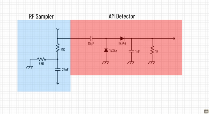
The RF sampler is just a simple resistive divider and a coupling capacitor. The goal is to knock the RF level down far enough that your analyzer or scope sees a safe signal while the tuner can still happily pass full power. Half watt resistors work fine here because the divider only sees a tiny fraction of the line power.
Build the divider in the air, right under the connectors. One end goes to the transceiver connector center pin, the other end goes to a convenient chassis ground bolt. The sampled node feeds through a small RF capacitor into the center pin of the first SMA jack. That capacitor blocks any DC that might be on the line, which is especially important if you are testing older tube gear or anything with high voltages. Keep the leads short and support the parts so they do not vibrate. When you are done, you have a permanent RF sampling port you can feed into a scope, frequency counter, or spectrum analyzer.
Building the AM detector circuit
The AM detector is built in a similar point to point style. This time you are not trying to pass an RF sample, you just want the audio envelope. A classic 1N34A detector diode, a load resistor, and a small capacitor are all you need. That basic circuit has been used in crystal radios for decades and still works well here.
Mount the second SMA connector next to the sampler port. Tie the detector to the transceiver connector and use another nearby ground bolt for the return. Feed the detected output to the new SMA jack. When you key up on AM, you can now connect an oscilloscope to this jack and view the modulated signal as an audio waveform instead of a high frequency RF trace. It makes it much easier to see clipping, distortion, or any strange audio behavior from a transmitter you are repairing.
Testing and using the new ports
With both circuits in place, reconnect the tuner to a dummy load. Before you button it up for good, run some low power tests. Start with your transmitter at a few watts on an HF band where the tuner and dummy load are comfortable. Connect a scope or analyzer to the RF sampler SMA and verify that you see a clean RF signal and that its level is well within the input rating of your instrument.
Next, switch over to AM mode and move the scope to the detector SMA. You should now see the audio envelope that rides on top of the carrier. Speak into the mic or feed an audio tone into the rig and watch the waveform. You will quickly get a feel for what good modulation looks like versus overdriving your audio. If you are experimenting with antennas, remember you can still use the tuner normally with your station while the sampler port feeds your test gear. For more antenna related tweaks, the writeups in the Antennas and Projects sections pair nicely with this mod.
Frequently Asked Questions
Will adding an RF sampler and AM detector change how my MFJ Versa Tuner works?
If you keep the sampler network high impedance and only tap a tiny amount of RF, the tuner will work just as it did stock. The resistive divider should look like a very light load in parallel with the existing circuit, so the tuner range and power handling stay effectively the same.
How much attenuation should I design into the RF sampler?
Aim for 40 to 50 dB of attenuation so that even at full power the sample is in a safe range for a scope or spectrum analyzer. That usually means the bottom resistor in the divider is only a tiny fraction of the total resistance, for example tens of ohms feeding thousands of ohms.
Do I have to use 1N34A detector diodes?
Classic 1N34A germanium diodes work well because of their low forward voltage and long history in AM detectors, but other small signal germanium or Schottky diodes can work too. If you change diode type, recheck the detected audio level and adjust the load resistor and capacitor to get the envelope you want.
Can I run full power into the tuner with this mod installed?
Yes, as long as you size the divider parts correctly. The sampler should look like a very light load in parallel with the existing line, so it does not affect the tuner's normal power handling. Always keep the tuner connected to a real load when transmitting and never use the sampler port itself as a termination.
Why use SMA jacks instead of BNC for the sampler ports?
SMA jacks are smaller, fit easily under the existing transceiver connector, and pair well with modern RF test gear like spectrum analyzers and SDRs. BNC works too if that matches your bench gear better, but SMA keeps the panel layout clean and is the more common interface on lab instruments.
Can I add this mod to other tuners or couplers?
In most cases, yes. The same approach works in many MFJ-style and similar tuners as long as there is room near the transceiver connector for two SMA jacks and a few small parts. The exact resistor values and capacitor ratings might change for different power levels, but the basic sampler-plus-detector idea stays the same.
Is this MFJ Versa Tuner mod worth doing?
For the cost of a couple of SMA connectors, a few resistors, a capacitor, and a pair of 1N34A diodes, you turn an ordinary tuner into a surprisingly capable piece of test gear. The mod is simple, completely reversible, and fits neatly under the existing hardware without changing how the tuner operates.
- You get a stable RF sample point for scopes, counters, and spectrum analyzers without breaking the RF line every time.
- The AM detector output lets you see modulation health at a glance while the tuner still feeds a real load.
- The project uses common parts and basic tools, so most hams who are comfortable soldering can pull it off in an evening.
If you want your workbench to pull double duty as an operating position and a simple RF lab, this MFJ Deluxe Versa Tuner mod is a very solid upgrade. Build it, label the new ports, and you will wonder how you managed without an RF sampler and AM detector sitting right in the middle of your station.